
Sometimes we DIY smart home people install smart devices and they don’t work. At first, we scratch our heads wondering what went wrong. Did I install it wrong? Is there a loose wire? Is the product defective? Wouldn’t it be nice to be able to test and configure smart devices before we install them? Especially considering some locations are hard to install devices in, and we often have to turn the breaker off. Well, you can test before installing. You just have to make a smart home test bench!
This page contains affiliate links. If you purchase an item using an affiliate link I will receive a small commission at no cost to you. Affiliates do not influence my recommendations. Read my disclosures for more information.
Table of Contents
What our smart home test bench can do
A few times over the years I’ve had some problems with installing and configuring smart light switches and smart bulbs. I’ve also had a few stop working over the years. Troubleshooting these things can be a pain. For example, I had a problem with a smart bulb I had installed outside of my house for a while. Having to stand outside in the rain troubleshooting it wasn’t very fun. Turned out it was defective (probably hit by the kids’ basketball one too many times). It would have been nice if I could have just put it next to my computer and tested it.
Other issues I’ve run into include:
- I’ve had to come up with some creative wiring for some of my 3-way switches.
- I’ve had a couple of issues with my hard to get to Aeotec Microcontroller light switches over the years.
- Another issue I run into is that I’ve got tight home network security and I isolate my IoT devices. This often requires me to white list devices before they can be put on the right network, which I do by MAC address. One thing I like about TP-Link smart devices is that they include the MAC address on the device. But most devices require me to connect them to my Wi-Fi network before I discover their MAC address, then white list, and then reconnect the device so they are on the right network segment. For devices connected to mains power, this usually means toggling the circuit breaker.
The smart home test bench we’ll build in this article solves all those problems and more. Specifically, it allows us to:
- Test and configure smart bulbs
- Test and configure smart light switches, dimmers, and relays, like the Brilliant Smart Home Control and the Shelly 1
- Configure and test 3- and 4-way light switches and dimmers
- Configure and test any smart device that requires mains power
Materials and tools I used to build the test bench
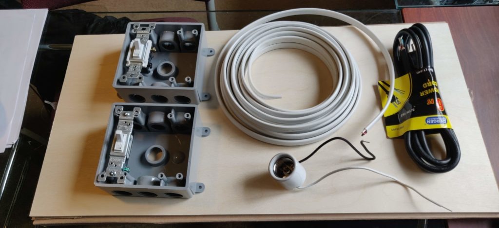
Here is a listing of the materials I used to build the test bench. Some of them I already had, however, I’ll include links where you can get them in case you don’t. If you are a tinkerer like me, you probably have some of these things or similar items that can take their place.
- Plywood — Something like this Birch Plywood on Amazon will do, or you can use some wood you have laying around. Depending in what screws you have, you might be better off with 1/2″ thick instead of 1/4″ thick.
- 2 Two-gang gang boxes — These will be used to house light switches and relays and the like that you’ll be configuring and testing. You need two to easily be able to replicate a 3- or 4-way setup
- 14/2 Romex wire with ground — I had some 14/3 Romex with ground laying around, but the one I linked to is one I’d recommend. 14/3 with ground has an extra wire that I won’t need. You don’t need much of it.
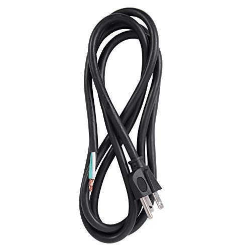
- A grounded extension cord — If you don’t already have that you can cut up, you can always buy one that comes pre-stripped, like this 3-wire appliance cord.
- Wire nuts – You’ll want these for wire connections.
- A lamp holder — The one I linked to here is a simple, inexpensive one. But you can use any lamp holder really, as long as you can get to the stripped cords and can easily secure it to the plywood.
- A light switch — It doesn’t have to be a smart switch at this point, as you just need it for testing.
- I secured the Romex cable to the plywood using these fasteners which I use for many things.
- You’ll also want some short wood screws for securing the gang boxes to the plywood and some screws for securing the light switch to the gang boxes.
Here’s a full listing of all the equipment needed and their current Amazon prices. Remember, you can use things you already have and substitute parts where they make sense for you.


You’ll probably also want to have some wire strippers, and maybe a line tester for safety. I recommend some good strippers and a tester in the smart home tools section of the HomeTechHacker shop. You’ll also want to have a spare light bulb for testing.
Put the test bench together
Editor’s Note: I am not an electrician and do not claim to be one. While I think this is a safe project if you are not comfortable dealing with mains voltage you should not proceed with this project. Read all of the instructions and be sure of what you are doing before starting and proceed at your own risk. Be safe!
Here’s how to put it together, step by step:
Step 1: Secure the gang boxes to the plywood
Just use some regular wood screws and place them on the plywood. You’ll want to keep the gang boxes close to each other so you can easily run wire between them (for 3- and 4-way switch testing).
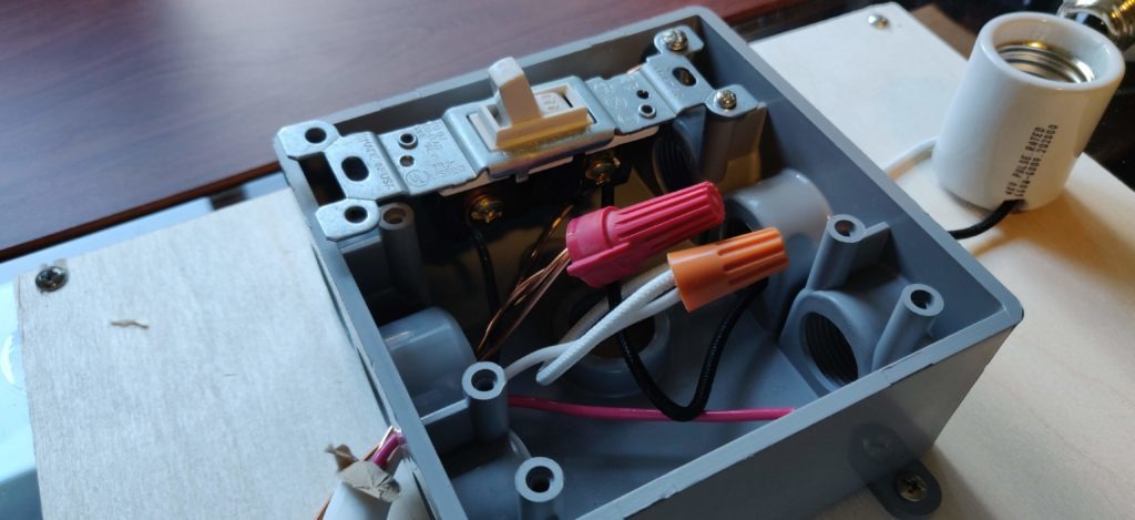
Step 2: Run wires from the Romex cable and lamp holder into the gang box
It should look similar to the picture below. You can ignore the red wire, as it is an extra wire I won’t be using because I used 14/3 Romex with ground instead of 14/2 Romex. You’ll want to strip the wires at the ends so you can easily connect them up later. Only use as long of a piece of Romex as you need. I made mine long enough to reach within a couple of feet of the outlet I’m going to use. It doesn’t have to reach all the way because I’ll be connecting it to the appliance cord, which is a few feet long.
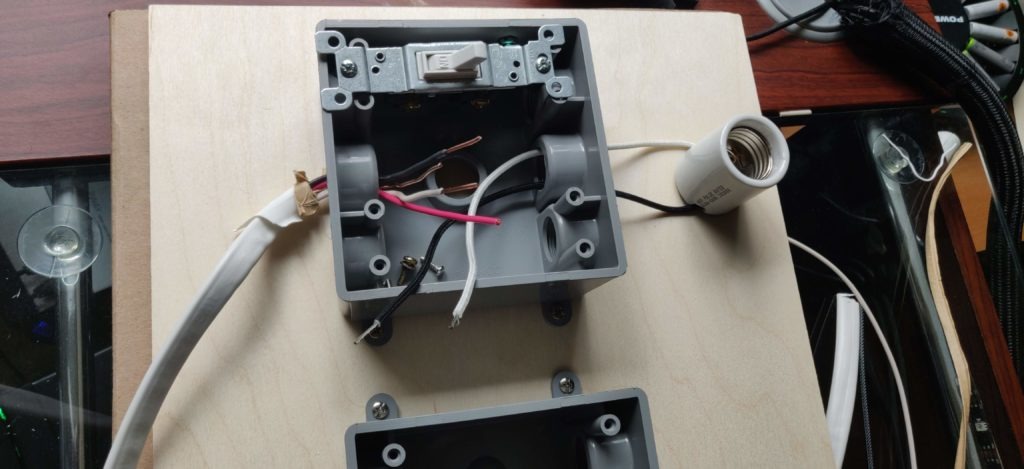
Step 3: Connect the Romex and lamp wires
For this step, connect the white (neutral) wire from the lamp to the white wire coming from the Romex using a wire nut. Cut an extra piece of ground wire (it can come from a part of the Romex you cut off earlier using) and connect one end to the ground connection on the light switch and one end to the bare ground Romex wire (using a wire nut). Lastly, connect the black (hot) wire from the Romex to one input on the light switch, and connect the black wire from the lamp (load) to the other input on the light switch. See the picture below for details:
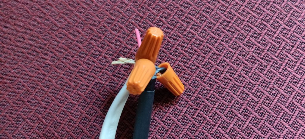
Step 4: Connect the Romex to the appliance wire
This part is straightforward. Using wire nuts, connect ground to ground (green or bare), white to white (neutral), and black to black (hot). Again, ignore the red wire in my picture as that wire is not used.
Step 5: Plug everything in and test!
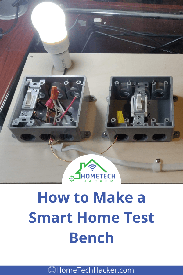
At this point, everything should be working. Double-check your connections. Then screw in a light bulb and plug the appliance module in. The light switch should turn the lamp on and off light a regular light switch would.
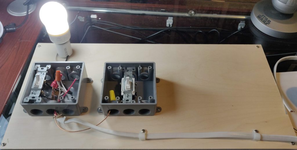
In the picture above, I used fasteners to secure the Romex wire outside of the gang box. I also ran an extra ground wire to the other gang box in case I want to do 3- or 4-way testing. To do that, all I have to do is add two wires (a hot wire and a traveler wire) that connects reaches from one gang box to the other.
Using this setup, I can now easily replace the switches with smart switches I’m testing or configuring, I can put in smart bulbs and test and configure them. I can also set up a Shelly relay or the like and test and configure it, along with many other smart relays and switches.
Keep in mind, when everything is plugged in, you have mains voltage exposed in the gang box, just like you would if it were in your wall. Exercise caution!
Final thoughts
There you have it! A simple and portable smart home device test bench that you can use to test, troubleshoot, and configure smart switches, smart bulbs, smart relays, and more. I wish I had built this before I installed a lot of my smart switches and relays. It sure would have made things simpler. But it has already come in handy a couple of times since I built it. It makes a great part of a smart home toolkit.
Do you have a smart home test bench? What do you use it for? What are some enhancements you would make to the one I built? Let me know in the comments or reach out to me on Twitter.

These posts are generally excellent and useful to a wide range of people, however I’ve found this post in particular resistant to translation into English – and by this I mean EU standards (which still match to GB equivalents).
Your posts do enjoy a global audience such that it would benefit many if you could perhaps spend a short period researching international descriptions which match US terms. Nobody would expect a full translation into different languages but when you swerve into generic description of wiring and US standards and terms, you are causing your overseas fans to be frustrated.
At an alternative extreme, you should definitely have a sturdy disclaimer when you start describing games with mains power, not forgetting that most countries have 220 volts, not the (tea adverse) 110 system you have.
I mention tea – ever wonder why tea in the US tastes horrible? Boiling water takes forever at 110v!!!
If nothing else, why not maintain a standard kit list, which would include your recommendations on equipment, but also the stuff mentioned here, which could also list equivalent gear in Emea and AP.
Loved the book!
Andrew,
Thank you for your feedback and compliments. I’m especially glad you liked the book (The Smart Home Manual). I should have another one coming out towards the end of the year.
I do realize my posts are read by people in many countries. Unfortunately, I barely have time to write the articles I do write. I usually write them from the perspective of my experiences, and thus, I don’t tend to write about specifics that are different in non-US countries. For most of my articles, it doesn’t make a difference. But for some, like this one as you have pointed out, it definitely does. It isn’t that I’ve forgotten that other countries are different, it’s just that I like to write from experience.
While most of my circuits are 120V, I do have some 240V circuits in my home to power larger appliances. You are right, though, the equipment I’ve used for this particular project is for 120V only. I’d have to replace some parts for higher voltages. I do have a bit of warning towards the end of the article about dealing with mains voltage. I probably should add something sturdier to the beginning as I have in a couple of other articles. I guess the difference I was thinking of here is that this bench is taking the place of starting with mains voltage, so anyone working on this would be aware of the issues, but that’s probably not the best assumption. I’ve added an additional disclaimer and put the previous one I had in the article in yellow.
I agree that maintaining a standard kit list is a good idea. I do have a listing of tools for smart home users in my smart home shop, and I have plans to write an article about tools sometime in the next few months, and then expand the tools page to include more items.
Again, thank you for your comments. You have given me some things to consider.